ESP32 Basics
The ESP32 is a low-cost microcontroller from Espressif with built-in Wi-Fi and Bluetooth. I reach for it whenever I need a connected device without stacking a separate radio module on top of a bare MCU. It shows up in hobby projects, prototypes, and plenty of shipped products because the boards are cheap, the community is large, and you can program them with the Arduino framework in minutes.
This post covers what is actually on the chip, what stays familiar across different ESP32 generations, and the first thing I do with every new ESP32-WROOM-32 dev kit: make an LED blink.
What is on the chip
At its core, the ESP32 is a system-on-chip (SoC) meant for connected embedded work. The classic ESP32 (the one on the common blue dev boards) includes:
- A dual-core Xtensa LX6 CPU running at up to 240 MHz
- Wi-Fi (802.11 b/g/n) and Bluetooth (Classic and BLE)
- GPIO pins you can use for digital input/output
- ADC for reading analog voltages, PWM for dimming LEDs or driving motors
- UART, SPI, and I2C for talking to sensors and displays
- Touch sensor inputs and I2S audio (on the classic chip)
Newer variants swap the CPU architecture or trim features to hit a price point, but the programming model stays similar. One rule applies to every version: the ESP32 runs at 3.3 V logic. Feeding 5 V directly into a GPIO pin can damage the chip. Level shifters exist for a reason.
What stays common across versions
Espressif has released several ESP32 families. The pin count, CPU, and radio features differ, but the dev boards all follow the same general layout.
| Family | CPU | Wi-Fi | BLE | Notes |
|---|---|---|---|---|
| ESP32 (classic) | Dual LX6 | Yes | Yes + Classic BT | WROOM-32 dev kits |
| ESP32-S2 | Single LX7 | Yes | No | Native USB OTG |
| ESP32-S3 | Dual LX7 | Yes | Yes | Vector instructions for AI workloads |
| ESP32-C3 | Single RISC-V | Yes | Yes | Lower cost, fewer pins |
Regardless of which family you pick, most dev boards share the same building blocks:
- A USB port and USB-to-serial bridge (CP2102 or CH340) for programming
- A 3.3 V regulator that steps USB 5 V down to what the chip needs
- EN (reset) and BOOT buttons to enter flash mode when uploads fail
- Two rows of header pins breaking out GPIO, power, and ground
- An onboard LED wired to a specific GPIO (the pin number varies by board)
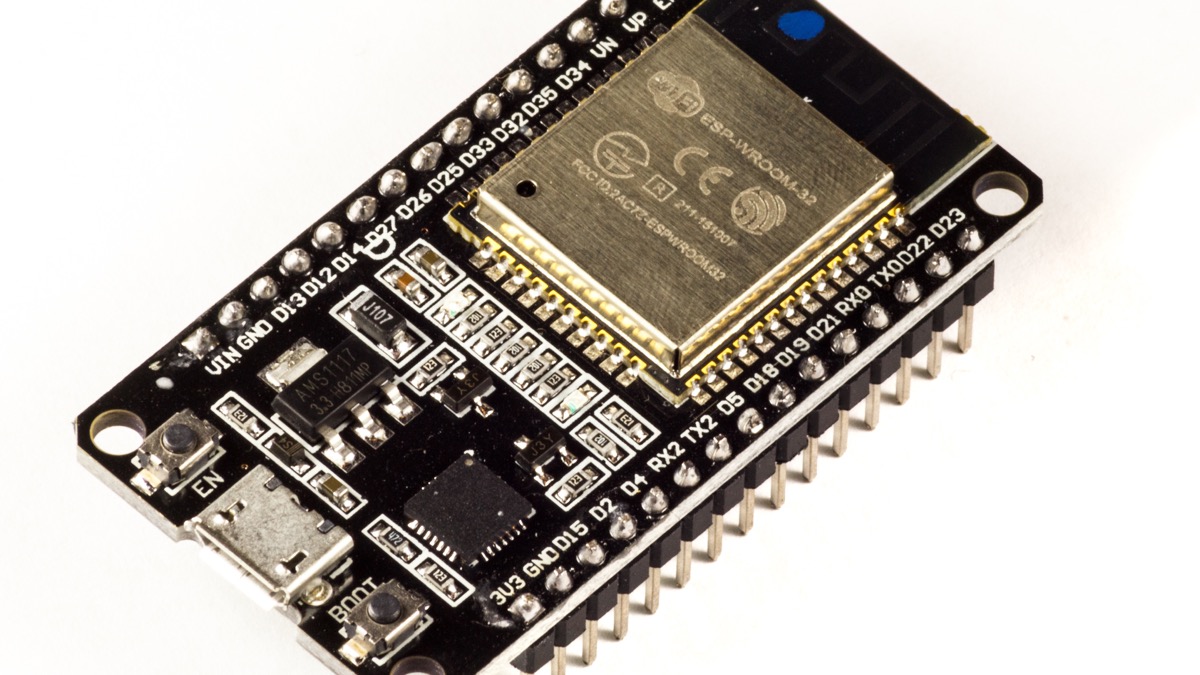
This post targets the classic blue ESP32-WROOM-32 DevKit. GPIO numbers differ on S2, S3, and C3 boards—always check the silkscreen label or the pinout card that came with your board before wiring anything.
Pins you need for the blink example
On most ESP32-WROOM-32 dev kits, the onboard LED connects to GPIO 2. You will also use GND (ground). If you wire an external LED on a breadboard, run the 3.3 V and GND rails from the board headers so everything shares a common ground reference.
Tooling
I use the Arduino IDE 2.x with the esp32 board package published by Espressif. Install it from Boards Manager, then select ESP32 Dev Module (or your exact board name) under Tools → Board. Plug in a USB data cable, pick the correct serial port under Tools → Port, and hit Upload. The IDE compiles your sketch, flashes it over serial, and resets the board.
Blink example — wiring
The simplest test uses the onboard LED—no breadboard required. For a clearer lesson in how GPIO works, I also wire an external LED:
ESP32 GPIO 2  ──► 220 Ω resistor ──► LED anode (+)
LED cathode (−) ──► GND
Use a 220 Ω resistor (330 Ω also works). The longer LED leg is the anode (+); the flat side of the LED package marks the cathode (−). Without a resistor, the LED can draw too much current and burn out.

If your board's onboard LED is already on GPIO 2, uploading the sketch below will blink that LED even without the breadboard setup.
Blink example — code
Create a new sketch in the Arduino IDE and paste this:
#define LED_PIN 2

void setup() {
  pinMode(LED_PIN, OUTPUT);
}

void loop() {
  digitalWrite(LED_PIN, HIGH);
  delay(500);
  digitalWrite(LED_PIN, LOW);
  delay(500);
}
setup() runs once when the board powers on or resets. It configures GPIO 2 as
an output. loop() runs forever: turn the pin high (3.3 V), wait half a
second, turn it low (0 V), wait again. That on-off cycle is what makes the LED
blink.
Upload the sketch and watch the LED. If you wired an external one, it should blink in sync with the onboard LED (when both share GPIO 2).
Troubleshooting
A few problems show up often on the first try:
- LED never blinks — wrong GPIO number for your board, LED wired backwards, or missing current-limiting resistor on an external LED.
- Upload fails — hold BOOT, tap EN, release BOOT, then retry. Also try a different USB cable (many charge-only cables lack data lines) and install the CP210x or CH340 driver for your serial chip.
- Board missing from the port list — almost always a driver or cable issue, not the sketch.
What is next
Once the LED blinks, I usually open the Serial Monitor at 115200 baud to confirm the board is alive, then move on to Wi-Fi or an I2C sensor. The blink sketch is small, but it proves the toolchain, the USB connection, and the GPIO pinout are all correct—which saves a lot of debugging time on the next project.